Thursday, March 26, 2015

AD9850 enhanced Arduino sine wave generator with keypad


AD9850 enhanced Arduino sine wave generator with keypad


After experimenting with the rotary encoder, I thought that entry of a frequency via a keypad of number keys would be a good idea.
So I modified the original setup by Andrew Smallbone and added this functionality to the device.

By pressing the blue button of the keypad, you can enter the frequency manually, and output by pressing the blue key again. You can still use the rotary encoder to modify the such set frequency.


Schematic


Thursday, February 26, 2015

AD9850 Arduino sine wave generator 0-40MHz

AD9850 Arduino sine wave generator 0-40MHz

Recently I got one of these cheap (6$) DDS modules from China, and started playing with.
You only need to send a decimal number to the unit, and this board generates a nice sine wave with the frequency of your number.

My first try was with a design and sketch I found on the internet.
Later I added functionality of entering the frequency by a number keyboard


Connect the board as described in the sketch

This is how the DDS board looks


ZOUT1 and ZOUT2 are the outputs for sine wave, the pins are labeled on the bottom of the board.


here is the code for Arduino.
I only copied this code, reference is in the code comments.

/*
 * A simple single freq AD9850 Arduino test script
 * Original AD9851 DDS sketch by Andrew Smallbone at www.rocketnumbernine.com
 * Modified for testing the inexpensive AD9850 ebay DDS modules
 * Pictures and pinouts at nr8o.dhlpilotcentral.com
 * 9850 datasheet at http://www.analog.com/static/imported-files/data_sheets/AD9850.pdf
 * Use freely
 */

 #define W_CLK 8       // Pin 8 - connect to AD9850 module word load clock pin (CLK)
 #define FQ_UD 9       // Pin 9 - connect to freq update pin (FQ)
 #define DATA 10       // Pin 10 - connect to serial data load pin (DATA)
 #define RESET 11      // Pin 11 - connect to reset pin (RST).

 #define pulseHigh(pin) {digitalWrite(pin, HIGH); digitalWrite(pin, LOW); }

 // transfers a byte, a bit at a time, LSB first to the 9850 via serial DATA line
void tfr_byte(byte data)
{
  for (int i=0; i<8; i++, data>>=1) {
    digitalWrite(DATA, data & 0x01);
    pulseHigh(W_CLK);   //after each bit sent, CLK is pulsed high
  }
}

 // frequency calc from datasheet page 8 = <sys clock> * <frequency tuning word>/2^32
void sendFrequency(double frequency) {
  int32_t freq = frequency * 4294967295/125000000;  // note 125 MHz clock on 9850
  for (int b=0; b<4; b++, freq>>=8) {
    tfr_byte(freq & 0xFF);
  }
  tfr_byte(0x000);   // Final control byte, all 0 for 9850 chip
  pulseHigh(FQ_UD);  // Done!  Should see output
}

void setup() {
 // configure arduino data pins for output
  pinMode(FQ_UD, OUTPUT);
  pinMode(W_CLK, OUTPUT);
  pinMode(DATA, OUTPUT);
  pinMode(RESET, OUTPUT);

  pulseHigh(RESET);
  pulseHigh(W_CLK);
  pulseHigh(FQ_UD);  // this pulse enables serial mode - Datasheet page 12 figure 10
}

void loop() {


  sendFrequency(2e6);  // freq 2MHz, type any value you wish in Hz, e.g. 123 will give 123Hz

  delay (10); // put delay or not, it doesn't matter 
  

}

Friday, February 6, 2015

LM75 Temperature Sensor On Arduino


Wire the LM75 in the above way. SDA goes on A4 and SCL on A5. 

Get the I2C library for arduino

Here is an example code which reads the temperature to the full degree C. 
//for lm75
#include <Wire.h>
#define SensorAdresse 0x48 // I2C address of the LM75
#define TEMP 0  // temperature register
char dataString[7]; // temp as string: (-xx)x.x
double temp; // temp as double
int tgtemp; //val to store temperature


//---------- setup devices----------------
void setup()
{Serial.begin(9600); //turn on serial port
   Wire.begin(); //turn on I2C
}

 //----------temperature measure section-----------------


double get_LM75_temperature(int device, int regx) 
{
  int8_t msb;
  int8_t lsb;
  int8_t msb1;
  Wire.beginTransmission(SensorAdresse + device);
  Wire.write(regx);
  Wire.endTransmission();
  Wire.beginTransmission(SensorAdresse + device);
  Wire.requestFrom(SensorAdresse + device, 2);
  if (Wire.available()) {
     msb1 = Wire.read();
     msb = msb1 << 1; 
     lsb = Wire.read();
  }
  
  lsb = (lsb & 0x80 ) >> 7; 
  Wire.endTransmission();
   tgtemp = (msb /2);


}//-------------end temp measure section------------


 void loop()
{
  temp = get_LM75_temperature(0, TEMP);
   
Serial.println(tgtemp);
delay (500);

}

Monday, December 8, 2014

Raspberry Pi power backup or UPS

A power failure on Raspberry Pi can be fatal for the SD card if the failure happens while data is written to the file system. In such case, not only the file system but even the SD card might be destroyed as reported on the internet.
power failure destroys SD card on Raspberry
I have spent some time and made a Raspberry Pi UPS with the following features:
  • operation of Raspberry is continuous
  • for longer power failures, the operating system shuts down
  • operating system reboots if power comes back
  • rechargeable lithium battery included and charging circuit is onboard
A full description can be found here:

Safe-Power for Raspberry PI


August 2015

 A version with updated firmware and redesigned PCB is now available.


Thursday, August 14, 2014

How to choose voltage regulators for AVR


In this article I'll try to give an overview of available Voltage regulators, their pros and cons and application hints.

There are two types of voltage regulators, linear and switching. If you are running your AVR from a battery with a voltage between 3V and 5V, you might not need a voltage regulator in some cases.


 Type 1 The linear voltage regulator


7805 linear regulator TO220
Linear voltage regulators like the uA7805 have been around for decades. For their naming scheme you mostly only have to remember the numbers.
e.g. uA7805, LM7805, MC7805 are all the same, except that they are from different manufacturers.


Advantages:
-easy to use (only 3 pins to solder)
-cheap
-"clean" output voltage if run from a DC source

Disadvantages:
-input voltage needs to be at least 2V higher than output for non low Dropout types
-the "excess" voltage *current is transformed to heat and heat sinks might be required
-there is a constant quiescent current flowing even without load

Working principle of linear regulators is to compare the input voltage with an internal reference, and direct the "excess" voltage and current into a transistor which transforms the energy into heat.
Therefore a linear regulator gets more efficient the less current flows and the less the difference between input and output voltage is. You can calculate the power your linear regulator converts to  heat by a simple calculation. P = (Uin-Uout) * I  Where P is the heat in Watt, Uin the input voltage in V , Uout the output voltage of the regulator, and I the current your circuit behind the regulator in Ampere.
Lets say you want to run your AVR with an LCD and a SD card and some LEDs from a 12V battery.
Your circuit draws 30mA = 0.03A. So the power dissipated is 12V-5V * 0.03A which gives 0.21Watt in heat for your linear regulator to dissipate. On a uA7805 in TO220 package, you would feel the body of the regulator getting warm. For small AVR circuits they are a good choice. Newer models like the LM1117 or the LP2950 are well suited. Personally I bought some for a good price: from Banggood Hongkong but they virtually sell everywhere. You will get them in any shop that sells electronic components.
Now lets say you have 24V input, and your circuit draws 0.5A. With the uA7805 you would need to dissipate nearly 10 Watt in the regulator. Mission impossible? Add a huge heat sink with cooling fan?
No, because there are better solutions available:

 Type 2 The switching voltage regulator


Switching regulators mostly need some additional parts around them. There is always an inductor, a capacitor, a diode and some resistors involved. Because of their higher efficiency they have become more and more popular over the last 20 years as prices for electronic components dropped considerably. As with linear regulators, there are a few advantages and drawbacks.


Advantages

-high efficiency up to 99%
-low heat dissipation
-input voltage can be lower than output voltage

Disadvantages

-electromagnetic noise is generated
-additional components are mostly needed
-circuit layout might affect performance and noise
-higher price

In short, switching regulators are mostly the better choice where energy efficiency, voltage step up, high Uin Uout difference or power outputs above 1 Watt are needed.
Some switching regulators come now pin compatible with the 78xx linear regulators and can be a direct replacement. These devices have all components integrated in the package. At the moment the high cost for such regulators limits their use for hobbyists. However there are now interesting alternatives based on well know LM switching regulators which come fully assembled for under 2$.
I have used several step down and a step up module from Banggood which are of good quality and the size of a stamp.
I will dedicate a special article about this step down regulator for less than 2$- shipping for free! At such prices it is nowadays possible for hobbyists to create small projects with energy efficiencies impossible to achieve some years ago.


Wednesday, June 6, 2012

avr solar counter

To log the harvested energy from your solar cells, you need a counter device. Here is my low cost counter (10$) with AVR micro controller, LCD and SD card for small solar cells upto 25W.
This is an ongoing project. Therefore more features and improvements will follow.

Features (so far):
-current upto 2A
-display of actual current
-display of harvested mA hours since begin of logging
-easy firmware update of the device through com port 

features not implemented yet:
-logging of hourly harvested energy to SD card
-upload of SD card data through serial connection (com port)


Time is displayed in the upper left,  iv = instant value for current - here 12mA in the evening of a rainy day, second line shows the total harvested Energy in mAh.


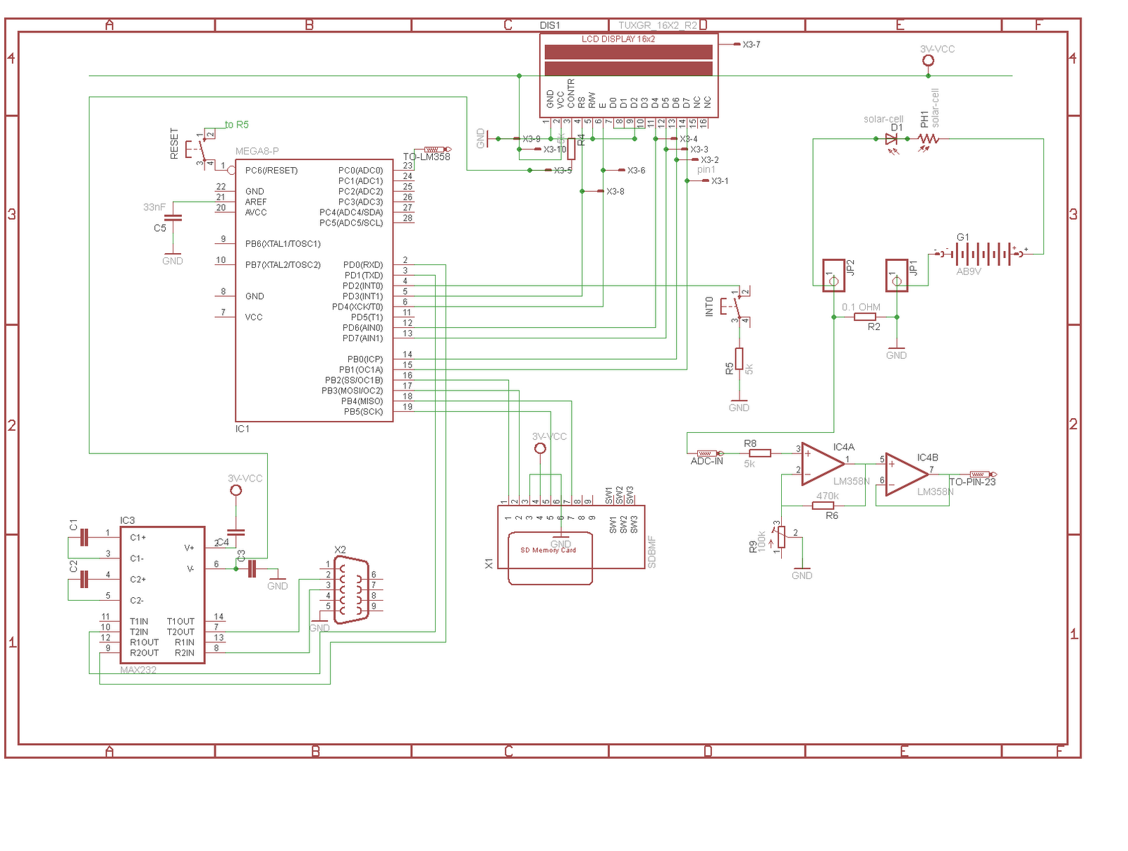
Current from the solar cell to the rechargeable battery is measured over R2. Resistor 2 is about 0.1 Ohm which is suitable for measurements upto 2A. If you wish to measure currents over 2A a smaller Resistor is needed otherwise the resistor will get too hot and will waste your energy. Calculate the power wasted by the resistor by the formula:
P= I² *R  At 2 Amperes and 0.1Ohm  this gives 0.4 Watt over the resistor.
The LM358 (2 op amps in a 8 pin package) amplifies the voltage of R2 and feeds the ADC of Atmels Atmega8. Note that Atmega 48, 88, 168 are pin compatible replacements.
Compiled hex file and source code in bascom are on the bottom of this page.

UPDATE:
new feature: SD card logging

The eeprom logging feature will not been implemented as the memory capacity of the standard 2 wire eeproms 24Cxx is insufficient.
Therefore logging to SD card will be the only choice. SD cards give a virtually unlimited storage space for this purpose. Data can be written directly to sectors and read out via the serial connection of the logger.
Electrically the card should be connected as shown in the schematic. Pin 1 to 7 are connected. When soldering the wires directly to the card, take care not to connect pin 7 and 8.

SD cards are specified for a voltage upto 3.6V. MMC cards are pin compatible and might work from 1.8V to 3.6V.
Source code and more description will follow.


Source code versions

version 1
 basic version, no logging feature, time, instant current value and collected energy will be displayed on LCD until next reset of the logger


 *********************** start of version 1 *************************

   $regfile = "m8def.dat"
$crystal = 4096000
$hwstack = 100
$swstack = 100
$framesize = 100


'******************* LCD-  ************************

 Config Lcdpin = Pin , Db4 = Portd.6 , Db5 = Portd.7 , Db6 = Portb.0 , _
   Db7 = Portb.1 , E = Portd.4 , Rs = Portd.3
Config Lcd = 16 * 2
Cursor Off


Dim Displayflag As Bit                                      'update display 1s set flag in timer1 isr

Dim Adcflag As Bit                                          'adc flag will be set to 0 by timer 1s
Dim A As Byte                                               ' count variable for ADCmeasure

Dim Second As Byte
Dim Minute As Byte
Dim Hour As Byte
Dim Day As Byte
Dim Hourvalue As Word                                       'value per hour
Dim Instvalue As Word                                       ' value of adc measurement

Dim Sumvalue As Long                                        'sum of all adc measurements

Dim Totalseconds As Long                                    'seconds since start of measurement
Dim Totalcharge As Long                                     'totalcharge since beginning of measurement
  ' - - - - - - - - Timer1 - - - - - - - - - - - - - - - -
Config Timer1 = Timer , Prescale = 256                      'config Timer1
Enable Timer1                                               'turn on t1
On Timer1 Isr_von_timer1                                    'verzweige bei Timer1 überlauf zu   Isr_von_Timer1
Enable Interrupts
Timer1 = 49535                                              'timer value to get 1s-- 65535´-16000 = 49535
 Second = 0

  ' - - - - - - - - int0 - - - - - - - - - - set clock


 On Int0 Int0isr                                            'on interrupt0 goto  INT0ISR
 Config Int0 = Falling
  Enable Int0
 Enable Interrupts                                          'Interrupts enabled


Config Pind.2 = Input                                       'int0 pin

Portd.2 = 1                                                 'enable pullup for Interrupt0 pin


  '------------adc-----------------


  Config Adc = Single , Prescaler = Auto , Reference = Avcc ' AVCC = 3V - for SD card


'------------main-------------------
    Do

  '- lcd values 1x /s

  If Displayflag = 1 Then
Totalcharge = Sumvalue / 3600                               'total charge until now
Locate 1 , 1
 Cls
Lcd Hour ; "H" ; Minute ; " iv " ; Instvalue ; "mA"         'display 00H00_iv_xxxxmA  displays minute, hours, instant value,
 Locate 2 , 1

 Lcd Totalcharge ; "mAh Total"                              '1024_T2048mAh
                                                            'will be updated next second again, timer1 resets flag
  Displayflag = 0


  End If

  '- count minutes up

 If Second = 60 Then

 Second = 0
 Incr Minute


End If

  '-  count hours up and calculate values
If Minute = 60 Then
Incr Hour
Minute = 0


End If

 '-count days up

If Hour = 24 Then
Hour = 0
Incr Day
End If


 '- measure adc once per second
If Adcflag = 0 Then Gosub Adcmeasure


 Loop


   '----------timer1  -------------

 Isr_von_timer1:                                            '
Timer1 = 49535                                              'Timer1 counts from 34285 to get 1second
Adcflag = 0                                                 'to read ADC value in main programm after timer interrupt
Incr Second
Incr Totalseconds

Displayflag = 1                                             'update lcd once per second in main program
Return

  '----------set clock  -------------
Int0isr:                                                    'to set clock

Incr Minute

Return

 '----------measure current -----------------
 Adcmeasure:
  Instvalue = 0                                             ' reset instvalue for next getadc

   For A = 1 To 2
Instvalue = Instvalue + Getadc(0)                           ' instvalue = mA
     Next A
                                  'instvalue is reset to 0 in timer1 isr

  Sumvalue = Sumvalue + Instvalue                           'adc sum of seconds since start of device

   Adcflag = 1                                              ' prevent main programm to do measurement again in this second


  Return


*********************** end of version 1 *************************

Wednesday, May 30, 2012

AVR 9V battery charger


Several devices use the 9V batteries and the rechargeable NiMh version is a good option. 
There are only a few commercial chargers for this type of 9V block available, and most of them are either expensive or of low quality and will damage your rechargeable battery.
Here comes my version of charger with the following features:
- input voltage from 12 to 42V
-constant current charge 
-micro-controller verifies the charge and switches charging off when a certain voltage of the battery is reached
- battery voltage displayed on LCD during charge
-low cost - about 10$ in total


Details:

The AVR micro controller measures the voltage of the battery over R4 and R3. Before measurement is taken, the charging voltage is switched off by the micro controller via Q1.
Q1 can be any P-channel FET, in my case I use an smd version in a SOT8 package which contains 1 N-channel and 1 P-channel FET. 
IC6 is just a 5V linear voltage regulator. In my case a LM1117 smd but any other 5V regulator would do the job. You can also use LF50, 7805, LP2950 etc.
The LCD is a standard HD47780 compatible LCD, in my case with 8x2. R7 for the LCD contrast, can be replaced by a fixed resistor connected to ground. Try values from 600 Ohm to 6k .
Charging current is limited to a maximum of 25mA by the resistor and LM117 combination at the output.


http://www.gutenberg.org


Here comes the bascom source code:

 $regfile = "attiny44.dat"
$crystal = 978149                                           '1001625                                                   500 in 8min56s = 536s /128x = 65536x timer =
$hwstack = 20
$swstack = 20
$framesize = 20


Dim A As Byte                                               'counter for 10x get ADC

Dim Voltage As Word                                         'calculated voltage from ADCwert
Dim Adcwert As Word                                         'For Battery Voltage
Dim Timecount As Word
Dim Displayvolt As String * 3                               'convert number to string for decimal point value
Dim Voltstring As String * 4
 Config Portb.0 = Output                                    'switches charging mosfet to 0
 Config Porta.6 = Input                                     ' set tri-state adcpin to prevent voltage


'----------timer1 for voltage check time--------------

  Config Timer1 = Timer , Prescale = 64                     'configure timer for 2 seconds
Enable Timer1                                               'enable timer
On Timer1 Isr_timer1                                        'after 2 seconds iterrupt routine is executed  Isr_von_Timer1
Enable Interrupts
 'Timer1 = 1337


 'lcd ----------------------------------------------
Config Lcdpin = Pin , Db4 = Porta.3 , Db5 = Porta.2 , Db6 = Porta.1 , _
   Db7 = Porta.0 , E = Porta.4 , Rs = Porta.5
Config Lcd = 16 * 2


't---------------------config ADC----------------------

   Config Adc = Single , Prescaler = Auto , Reference = Avcc
   Start Adc


'(

 if voltage =  0 then Lcd Insert Battery
 if voltage < 10v then start charge via Pb.0 = 0
if voltage > 10v then display "battery full" and finish


')


'----------main loop----------------------------
  Do


  Wait 2


  Loop


  Isr_timer1:


   '----------Measure battery voltage------------

    Portb.0 = 0
    Config Portb.0 = Input                                  'measuring of voltage every 2 seconds while not charging ,switch mosfet off, no charge
  Waitms 5


    Adcwert = 0
   For A = 1 To 10
    Adcwert = Adcwert + Getadc(6)                           'pin7
    Next A


  '---------display state ---------------
     If Adcwert > 3700 Then
    Cls
                                      'when voltage is over 370= 10V, battery full, end charge


    Lcd "full"
    End If

  If Adcwert = 0 Then
  Cls

 Locate 1 , 1
 Lcd "insert"
 Locate 2 , 1
 Lcd "battery"
 End If


 If Adcwert < 3701 And Adcwert > 0 Then                     '3701 =10V

  Config Portb.0 = Output
    Portb.0 = 1                                             'Switch Mosfet On , Charge
 Cls

  Voltage = Adcwert / 37
      Displayvolt = Str(voltage)
            Voltstring = Format(displayvolt , " 0.0")

            Locate 1 , 1
            Lcd "charging"
            Locate 2 , 1
    Lcd Voltstring ; " V"


    End If


    Return


    Finish:


   Portb.0 = 0                                              'switch mosfet off, no charge


    Cls

    Lcd "full"
    Wait 2

    Return